Electrical insulation performance of cables with thermoplastic and thermosetting materials under simulated heating conditions caused by nearby fires in nuclear power plants
Fire accidents are a significant evaluation target in the safety management of nuclear power plants (NPPs). NPPs employ various electrical cables for power supply, instrumentation, and control. During a fire event, these cables may experience combustion and failure because of thermal damage. Such an event may impair the safe shutdown capability of NPPs. Depending on the thermal properties of the polymer materials used for insulation and sheath, the cables used in NPPs can be classified as thermoplastic (TP) cables, thermosetting (TS) cables, and TP/TS hybrid cables. Although the electrical insulation performance of TP and TS cables under elevated temperature conditions during fires has been well investigated, the performance of Japanese TP/TS hybrid cables, particularly those classified as flame-retardant cables, has not been thoroughly studied.
The Regulatory Standard and Research Department, Secretariat of Nuclear Regulation Authority (S/NRA/R), has been conducting a research program on fire safety from 2021 to 2024 [1][2]. As part of this program, University of Tsukuba conducted a series of tests to examine the electrical insulation behavior of cables during fire events [1].
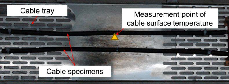
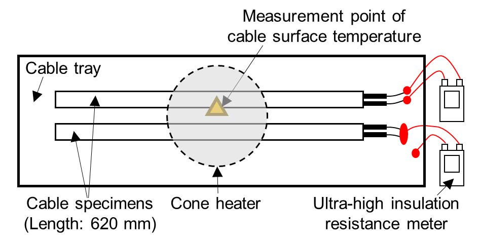
In the tests at University of Tsukuba, two Japanese flame-retardant cables were used: a polyethylene-insulated, nonhalogen flame-retardant polyethylene-sheathed cable (a TP/TS hybrid cable) and a crosslinked polyethylene-insulated, nonhalogen flame-retardant polyethylene-sheathed cable (a TS cable). The cables were subjected to heating tests for up to 2 h to simulate the elevated temperatures caused by fires near the cables. Although polyethylene is considered a TP material, the non-halogen flame-retardant polyethylene sheath in both TP/TS and TS cables was classified as a TS material in this study because of its propensity to foam upon heating and its behavior that is similar to that of TS materials. The test apparatus used in this test is shown in Figure 1. The cone heater set temperature was varied between 610°C and 770°C. The cable surface temperature was monitored during the tests using a noncontact infrared thermometer. As shown in Figure 2, the electrical insulation resistance was measured every 5 s using an ultrahigh insulation resistance meter, applying a voltage of 500 V and covering a measurement range of 2.5–1010 MΩ.
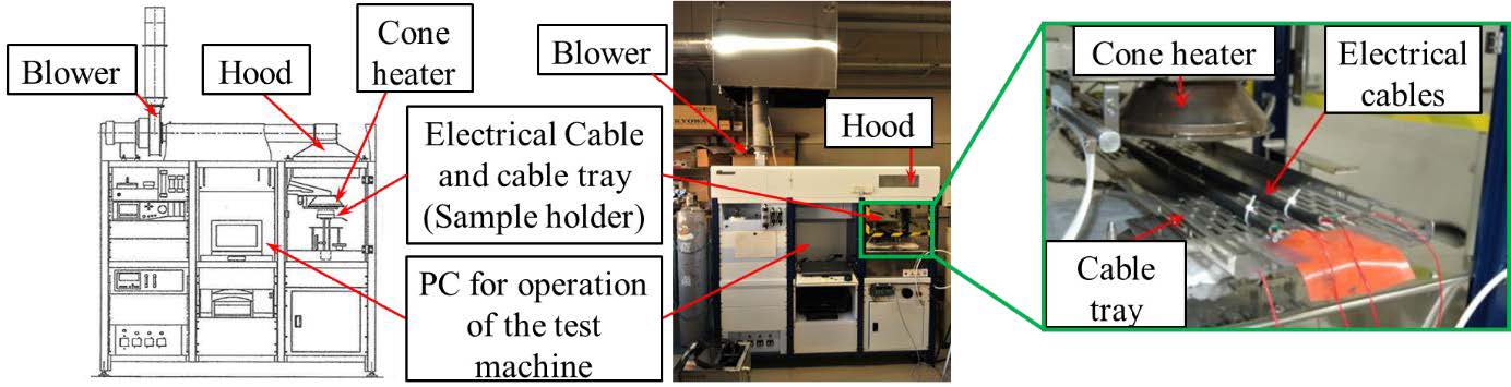
“Heating test machine using a cone calorimeter.” by IOP Publishing is licensed under CC BY 4.0.
 |
 |
|
Figure 2: Appearance and schematic diagram of the heating test system using a cartridge heater. This figure, "Appearance and schematic diagram of the heating test system using a cartridge heater.", is adapted from "Electrical insulation performance of flame-retardant electrical cables with thermoplastic and thermosetting materials for nuclear power plants" by IOP Publishing, used under CC BY 4.0.
|
|
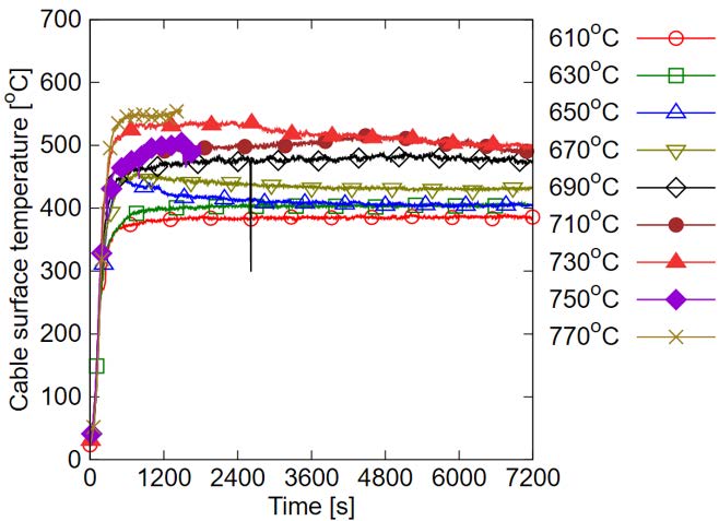
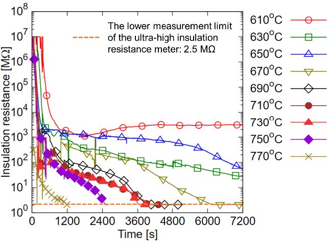
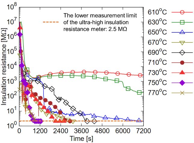
S/NRA/R analyzed the tests results [2]. Figures 3 and 4 show the change in the cable surface temperature and the insulation resistance between the conductors of the TP/TS and TS cables as a function of time during the heating tests. Initially, as the cable surface temperature increased, the insulation resistances of the cables decreased. As the set temperature of the cone heater increased, the insulation resistance decreased rapidly to the lower measurement limit.
 |
 |
|
Figure 3: Change in the surface temperature and insulation resistance between the conductors of the TP/TS hybrid cables as a function of time during the heating tests. (TP: thermoplastic and TS: thermosetting) This figure, "Change in the surface temperature and insulation resistance between the conductors of the TP/TS hybrid cables as a function of time during the heating tests.", is adapted from "Electrical insulation performance of flame-retardant electrical cables with thermoplastic and thermosetting materials for nuclear power plants" by IOP Publishing, used under CC BY 4.0.
|
|
 |
 |
|
Figure 4: Change in the surface temperature and insulation resistance between the conductors of the TS cables as a function of time during the heating tests. This figure, " Change in the surface temperature and insulation resistance between the conductors of the TS cables as a function of time during the heating tests.", is adapted from "Electrical insulation performance of flame-retardant electrical cables with thermoplastic and thermosetting materials for nuclear power plants" by IOP Publishing, used under CC BY 4.0.
|
|
The insulation resistance of both the TP/TS and TS cables reached the lower measurement limit under test conditions where the surface temperature of the cables exceeded approximately 400°C. Such behavior is similar to the characteristics of cables with different insulating materials, as reported in previous studies [3]. In contrast, the time required to reach the measurement limit was longer for the TP/TS hybrid cable than for the TS cable. This difference was attributed to the differences in the insulation materials. S/NRA/R will conduct further heating tests with the typical Japanese cables used for NPPs and analyze the experimental results to clarify the effect of the insulation materials on the electrical insulation performance.
This text is adapted from "Electrical insulation performance of flame-retardant electrical cables with thermoplastic and thermosetting materials for nuclear power plants" by IOP Publishing, used under CC BY 4.0.
References
[1] The Regulatory Standard and Research Department, Secretariat of Nuclear Regulation Authority, “Safety research plan for 2024 fiscal year,” 2024. https://www.nra.go.jp/data/000474194.pdf. (in Japanese)
[2] M. Takizawa, H. Kabashima, and A. Matsuda, “Electrical insulation performance of flame-retardant electrical cables with thermoplastic and thermosetting materials for nuclear power plants,” Journal of Physics: Conference Series, vol. 2885, 012018, Proceedings of 4th European Symposium on Fire Safety Science (ESFSS 2024), 2024. doi:10.1088/1742-6596/2885/1/012018
[3] Sandia National Laboratories and U.S. Nuclear Regulatory Commission, “Cable Response to Live Fire (CAROLFIRE) Volume 2: Cable Fire Response Data for Fire Model Improvement,” NUREG/CR-6931, vol. 2, SAND2007-600/V2, 2008.
Makoto Takizawa
NRA
takizawa_makoto_hf5@nra.go.jp